Atomic Clocks FAQ

Yes. All of our ISO certifications are available on our Quality page.
Yes, there is an technical note for the RMO Rb model, though applicable for any other Rb model, which explains the outer temperature increase of a Rb unit within a given system configuration and the optimization of the heat dissipation through a heat sink device or radiator. The mRO-50 does not need a heat sink due to its low power consumption.
If you have any specific requirement verification test request, please fill out this document and send it to the contact at the bottom of the form.
Cold storage should be performed with a stable humidity rate of max. 30-60%. There are no issues for hot storage.
Storage time under current environment – i.e., humidity up to 60%RH – is not limited. For a long period of storage under severe climatic conditions (e.g., tropical environment, >40°C and >85%RH), we recommend that customer request for a hermetically sealed package. This package is also ESD safe, and should be removed just before operating the Rubidium clock.
Other storage options such as inert gas package filling or vacuum packaging is also possible.
The rubidium lifetime (or reliability) is 20 years. Click on MTBF data for more information.
Click on PSDS document . Since we are strictly selling Rubidium product and not Rubidium material, the document is named PSDS (Product Safety Data Sheet) rather than MSDS (Material Safety Data Sheet). The PSDS document contains information related to Q&A in handling/shipping of Rubidium (Rb) oscillators and system products containing Rb oscillators.
The PicoTime is delivered with acquisition software which provides raw data for Allan deviation plotting and computing applications. For data analysis, you can request information about the STABLE32 timing performance management program.
Check out these connection instructions.
Yes, but with 3 initial phase alignments: 0s, 33ns or 66ns.
Check the information in the related Operating Manual. The OOL output is slightly different for each Rubidium clock.
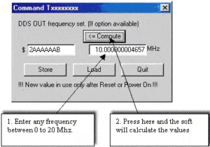
As illustrated below, the SRO mon.exe program allows you to enter a frequency between 0 to 20 MHz and the program will automatically compute the values.
+/-100ns
The PicoTime™ generates ASCII file data. A third-party program can be used to retrieve and process this data for timing performance management. To request a quote for such a third-party program, please contact us.
The GXClok-500 should manage a leap second correctly with “60” as second indication. However, there is not often an occasion to test it. The same routine program behaved correctly during the last leap second event.
The only way to know if there is a leap second pending is to communicate directly with the ublox’s GPSGlobal Positioning System is a navigation satellite system. See also LEA-6T receiver that is integrated into the GXClok-500. We are not equipped to test nor simulate a leap second situation.
Nonetheless, if the GXClok-500 misses a leap second, the GPRMC NMEA message will be false during 15 seconds for instance, then the message will follow the GPS’ receiver indications.
ASCII commands over RS-232.
+/-200ns.
The smart SRO has the capability to adjust the 1PPS output from 0-1 sec through its internal 1ns-resolution comparator for phase/time alignments. The adjustments can be made thru the RS-232 commands. Check the instructions in the Operating Manual.
A typical holdover performance is illustrated below.
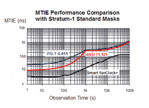
Request our What-If Holdover Simulator.
Click here for Safran’s Atomic Clocks & Oscillator products compliance status to the Directive 2011/06/U (RoHS).
The full text of the Directive 2011/65/EU on the restriction of the use of certain hazardous substances in electrical and electronic equipment (RoHS) can be obtained here.
Check with www.itt.com. The P/N should be DBM25-S1AON for chromate shells and DBM25-S1AON-A197 for tin shells
A tracking (or learning) time of 24 hours is required to achieve a 1us/24hr performance, allowing the average frequency to be successfully saved in the EEPROM inside the SRO.
If the tracking is stopped after 12 hours, the SRO goes back to the factory setting frequency, affecting the holdover (or free running) performance. Ideally the SRO’s holdover tests is as follows:
- Power on the SRO and let it stabilize for 1 day.
- Start the tracking process by HW (hardware) or SW (software). Sync or no sync mode has no influence.
- Let it track for at least 24 hours.
4) Put the SRO in holdover mode by stopping the 1PPSREF or optionally removing the GPS antenna. Stopping the tracking by HW or SW will have a different holdover performance, as a sudden frequency jump to the last frequency value will be stored in the EEPROM. If the 1PPSREF is stopped during the tracking process, the SRO will go in holdover mode with a smooth (or negligible) frequency jump, which will be the last frequency value stored in the EEPROM. Below is the basic concept:
- Long period of tracking, many days, 24 hours frequency saving will be activated: thus no difference in holdover performance
- Short period of tracking, <1day, 24 hours frequency saving will not be activated: thus a large difference in holdover performance
Notes:
- The frequency learning during the tracking process is related to the command FS (frequency save)
- Check if the 24 hours frequency saving is activated with the “FS9” command. The answer should be 1.
- If 24 hours are too long for the frequency learning, you may test with the FS2 or FS3 command during the tracking process. This command must be sent just before going back to the holdover mode by HW or SW.
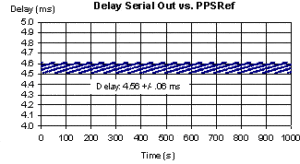
The time message available through the RS-232 BTx command is delayed a few ms from the PPSInt (internal PPS reference). If the Sync mode is ON, the time delay performance with the software 1.06 is illustrated below. If your application requires an improved time delay performance, please contact us.
- No Ultrasonic and Megasonic cleaning
- No reflow process : soldering with ROHS solder wire SAC305 manual soldering. Below 10s @ 260°C on each pin.
- PCB cleaning : Manual isopropanol cleaning with a brush
- Do not need to solder the mRO-50 on the PCB board
- SpT advises to glue it on the PCB with an epoxy adhesive 2216 type
The pin #1 (IN analog frequency adjustment) must not be connected to any voltage potential if not used (not grounded) (instructions under section 4.8.4 Center frequency adjustment of the Manual)
- To implement an analog frequency adjustment for disciplining the mRO-50 the process is the same as disciplining an OCXO
- To implement a digital frequency adjustment for disciplining the mRO-50, the process workflow can be provided with a request to assist the customer with its implementation.
The file can be provided to interested parties through a support request.


